BJT Amplifiers Posted on Jun 11, 2022
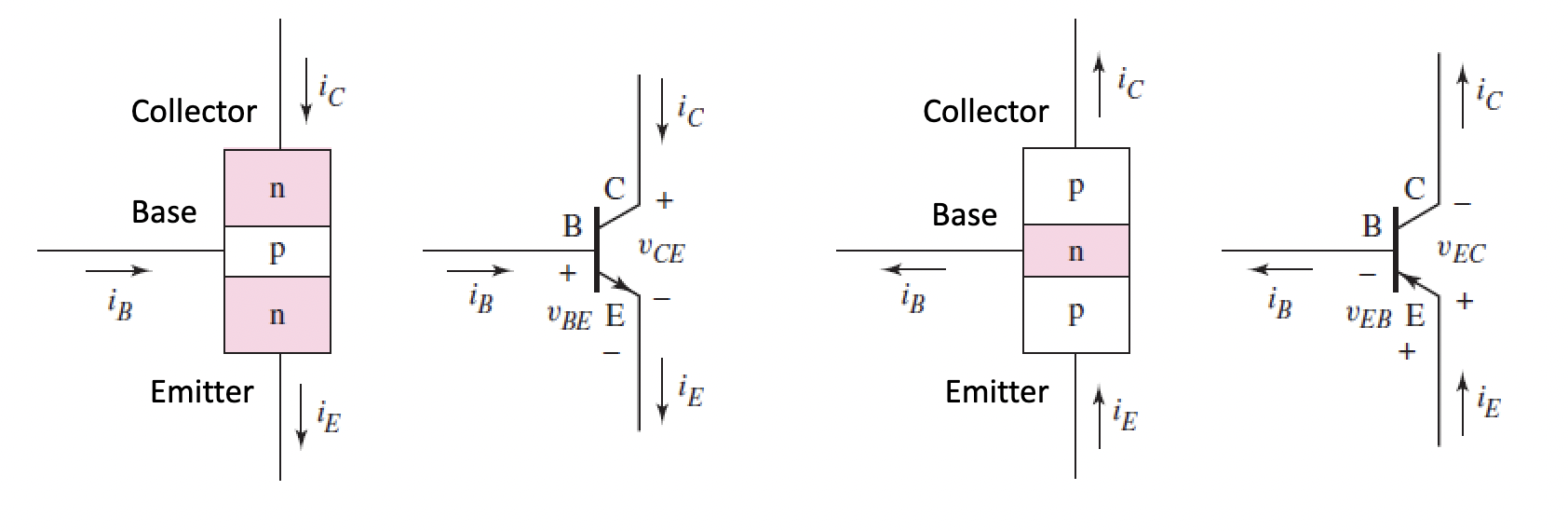
BJTs NPN vs PNP BJTs Analogue design focuses on the forward-active mode of BJTs (B-E forward biased, C-B reverse biased) β is the common-emitter current gain, usually ~150
$$β=\frac{i_C}{i_B}, i_C=βi_B$$
$$i_E=i_B+i_C$$ α is the common-base current gain
$$α=\frac{β}{β+1}, β=\frac{α}{1-α}$$
$$i_E=\frac{i_C}{α}$$
For a large β:
$$α\approx 1$$ For a BJT (npn and pnp respectively), we take:
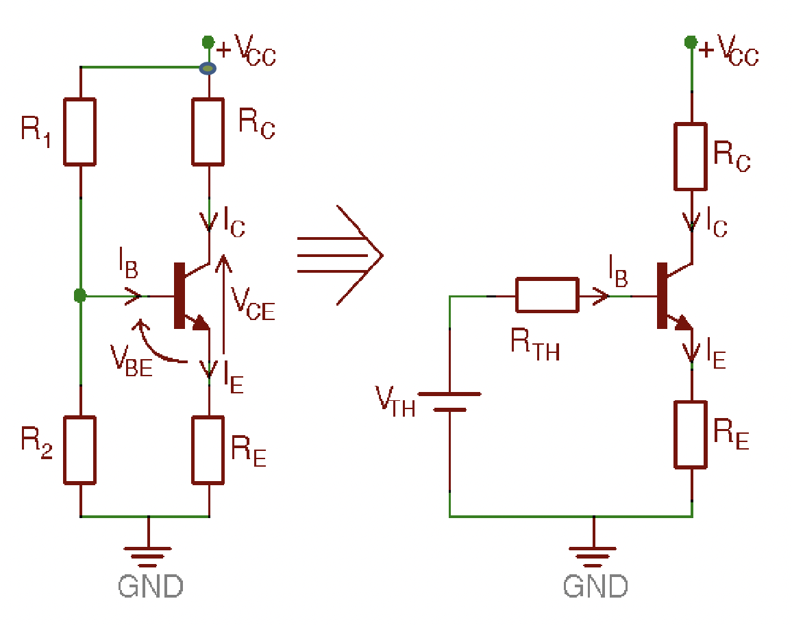
$$v_{BE}=0.7v, v_{EB}=0.7v$$ DC analysis We want to set up a Q-point (quiescent) to a certain specification, we do this by setting resistor values Voltage divider (Four Resistor) bias circuit, and it's Thevenin equivalent circuit Consider:
$$R_{Th}=R_1||R_2, V_{Th}=V_{CC}\frac{R_2}{R_1+R_2}$$
If split power:
$$V_{Th}=(V_{CC}-V_{EE})\frac{R_2}{R_1+R_2}$$ Using this Thévenin equivalent circuit:
$$I_B=\frac{V_{Th}-V_{BE}}{R_{Th}+(1+β)R_E}$$ Stabilising I_C by design: we can choose a ‘small’ R_Th i.e.
$$R_{Th}=\frac{βR_E}{10}$$
This lets us simplify:
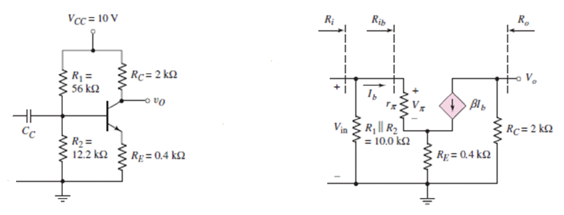
$$I_C\approx I_E$$ AC analysis Four resistor bias circuit transformed for AC analysis. Voltage form of the above:
$$βI_b\implies g_mV_{be}$$ To transform a circuit for AC analysis:Replace capacitors with short circuits Replace DC volt sources with shorts to ground Replace the BJS with the hybrid π model shown above V_T is the thermal voltage (assume =25mV), g_m is the transconductance of the BJT
$$g_m=\frac{I_{CQ}}{V_T}=40I_{CQ}$$ Internal resistance
$$r_π=\frac{βV_T}{I_{CQ}}=\frac{β}{g_m}$$ Input impedence @ base
$$R_{ib}=\frac{V_{in}}{i_b}=r_π+R_E(1+β)$$
Impedence @ ri
$$R_i=R_{ib}||R_1||R_2=(r_π+R_E(1+β))||R_{Th}$$ Voltage in
$$V_{in}=i_bR_{ib}=i_b(r_π+R_E(1+β))$$
Voltage out
$$V_o=-βI_bR_C$$
Therefore: Voltage gain :
$$A_v=\frac{V_o}{V_{in}}=\frac{-βI_bR_C}{i_b(r_π+R_E(1+β))}=\frac{-βR_C}{R_E(1+β)}$$
For large β:
$$A_v=\frac{-R_C}{R_E}$$
Note: negative sign implies 180° phase shift (inverting) 

